3-16-2005
Preface to “Induction System Improvement on the
Lancair 360”,
The
following report was published in the Lancair Network News (LNN) in 2000
shortly after having completed the upgrade.
Improving the induction system was the first of two performance
enhancing changes made to N91CZ. The
cooling system was tackled in 2004 and netted an additional 5 knot speed
increase along with dramatically cooler temperatures.
Induction System Improvement on the Lancair 360
8-21-2000
Chris Zavatson
It is rare to get something for nothing. The same holds true when trying to go faster in our already speedy little Lancairs. However, I just recently completed the most significant change to my 360 since it has been flying that has bent this rule just a little. High altitude cruise speed increased 10 kts and sea level power available at for takeoff increased 16 hp -all this simply by changing the design of the carburetor air box and filter.
N91CZ
has been flying for three years and has accumulated 500 hours. Aircraft performance has always been amazing,
especially compared with anything I had previously flown, but I knew there was
more untapped speed available. I have a
carbureted Lycoming O360A1A installed, completely stock as delivered from the
factory in
Back
to the story: Towards the latter portion of initial construction I wasn’t
completely satisfied with the induction system but was not feeling up to the
task of redesigning the whole thing. I
had used the Lancair supplied air box, plumbed in carb-heat and installed a
filter. The foam filter was held between
wire mesh screens in the air box. I had
installed a 3 inch diameter tube section in the cowling for the carburetor air
inlet, but found no easy way to seal this to the non round cross section of the
air box. I flew with this set-up for
nearly three years during which time four events changed my cruise speed. The first three were fairly painless: Painting the plane, reducing the spinner to
prop gap and adding AvBlend to the oil each added just over 1 knot. This put us at 199 KTAS, just short of that
nice round 200 but still respectable. The fourth event that affected our cruise
speed prompted me to get working on a new induction system. When we had to replace our 300 hour factory
new O-360 for another factory new O-360 because of Jet fuel contamination, we
were disappointed to emerge with a 3 knot drop in cruise speed. We had slipped back to 196 KTAS due to bad
luck with contaminated avgas and engine manufacturing tolerances.
From
time to time, I had pondered the idea of completely redoing the intake system
in order to first replace the foam filter and secondly to seal the induction
system to the cowling. Changing the foam filter for something a little better
such as a K&N filter would improve filtering and lower the inlet
restriction. I had never
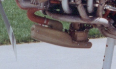
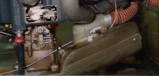
Original Air Box
considered
flying without a filter as an option.
(After retrieving little pebbles up to 1/16” in diameter out of the
filter, I was glad the filter was in place.)
The second goal of sealing the induction system would allow me to
capture ram pressure, which is significant at our speeds. I couldn’t stand
going slower than I had before so I took up the air box project in
earnest. I searched through a K&N
catalog to find the largest size filter I could physically fit in the available
volume. The filter area opens to about 5.5 times the inlet area and
greatly reduces losses across the filter element. There isn’t a lot of space given how tight
the cowling hugs the engine.
Nevertheless, I was able to squeeze out a larger surface area by
significantly canting the filter forward.
The total filter area was doubled over the previous design and the
filter media improved enormously in switching from foam to K&N. I built up a plug around the volume of my
chosen filter, the intake requirements of the carburetor and carburetor heat
access. This plug could be bolted up to
the carburetor to check for any interference and to verify alignment with the
air intake. The next step was molding
the plug. The mold was made in five
pieces, which allows me to produce interlocking parts. The air box had to be made up in three pieces
given its geometry; otherwise the overlapping sections would not allow disassembly. The large area of the filter necessitated
relocating the carburetor heat inlet port.
Doing so made the plumbing a bit more difficult. In the previous design a single large hinged
flap would open carb heat and block off intake air simultaneously. Now this was no longer possible. A butterfly valve at the back of the air box
now controls heated air, while a separate hinged valve behind the filter shuts
off ram air. If you don’t block the ram
air intake, carburetor heat air will be forced to flow backwards from the air
box to the heat muff and into the cowling.
The two valves are connected with a linkage that actuates both valves in
unison.
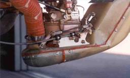
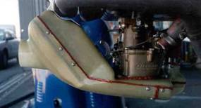
New Air Box
The
performance results were as good as I could have hoped for; I gained two inches
of MP at the lower altitudes. This
tapers down to 1.2 in at 17,500’. My
cruise speed increased 5 kts down low and 10 kts up high. The chart compares full throttle manifold
pressure readings for the new air box with standard atmospheric pressure, the
Lycoming zero ram engine performance (shows induction losses) and the old air
box. The difference between the new air
box curve and the zero ram performance curve reveals how much ram pressure is
being captured. Ram pressure even
exceeds induction losses except when IAS is low (take-off and high
altitude).
An
additional benefit is improved cooling despite the higher power being
produced. Any pressure escaping from the
inlet to air box transition pressurizes the cowling below the engine. This of course opposes cooling air coming
through the cooling fins from above.
I
have looked at many induction systems on 235/320/360s and have found this to be
one of the most varied installations on our airframes. Many installations start out with some sort
of sealed induction system. Some have
filters others do not.
I
found it quite interesting to be able to compare the before and after
data. More speed is always good. More speed for free is even better.